Output
CircuitVerse features different output elements listed below:
Output
When the Output circuit element is connected to another circuit element, it displays the relevant output in binary form.
Properties that can be customized in the PROPERTIES panel include: BitWidth
You can verify the behavior of the Output circuit element in the live circuit embedded below:
Digital LED
The Digital LED element switches between on and off depending on the input applied to it.
- Input of
1turns on the LED - Input of
0turns off the LED.
The digital LED does not recognize inputs of a length other than one bit. For your project, if the color must be changed based on the applied input, use the RGB LED element.
Properties that can be customized in the PROPERTIES panel include: Color*
*Color of a LED can be changed using color name, HEX color codes, RGB and HSL values
You can verify the behavior of the Digital LED circuit element in the live circuit embedded below:
VariableLED
The variableLED element changes between 256 intensities based on an 8-bit input. It has a:
- Maximum intensity when the input applied is
11111111 - Zero intensity when the input applied is
00000000.
You can verify the behavior of the variableLED circuit element in the live circuit embedded below:
RGBLED
Unlike the digitalLED or variableLED circuit elements, the RGBLED element can display a wide variety of colors. It takes three 8-bit inputs which describe the intensity of red, green, and blue color respectively.
TIP: Use a color picker to find the corresponding R, G, and B values and then use a decimal-to-binary converter to find the corresponding 8-bit value that must be entered for each input.
You can verify the behavior of the RGBLED circuit element in the live circuit embedded below:
SquareRGBLED
While the SquareRGBLED works similarly to the RGBLED, the SquareRGBLED differs in its shape and includes pin lengths that can be customized in the PROPERTIES panel. These additional features make SquareRGBLEDs ideal for simulating arrays of pixels.
Properties that can be customized in the PROPERTIES panel include: Pin Length
The live circuit embedded below illustrates how an array of pixels may be programmed to display an image. The circuit design includes a LED buffer subcircuit that manages the circuitry controlling the LEDs. The ability to vary the pin length of the square RGB LED element makes the design clean and easy to read. To make the design more comprehensible, the pins for different square LEDs must remain in the same vertical order as the LEDs themselves (i.e. the top pins must correspond to the top LED).
HexDisplay
The HexDisplay is more simple to use than the SevenSegDisplay and SixteenSegDisplay circuit elements. Since it takes a 4-bit input and can display integers 1 through 9 and the letters A through F, there is less room for customization.
The input bits do not control the individual segments ( as it is not possible to control six segments with only four bits). The hex display simply recognizes the integer/letter that a given input corresponds to and displays the character. The display character thus does not need to be programmed.
You can verify the behavior of the HexDisplay circuit element in the live circuit embedded below:
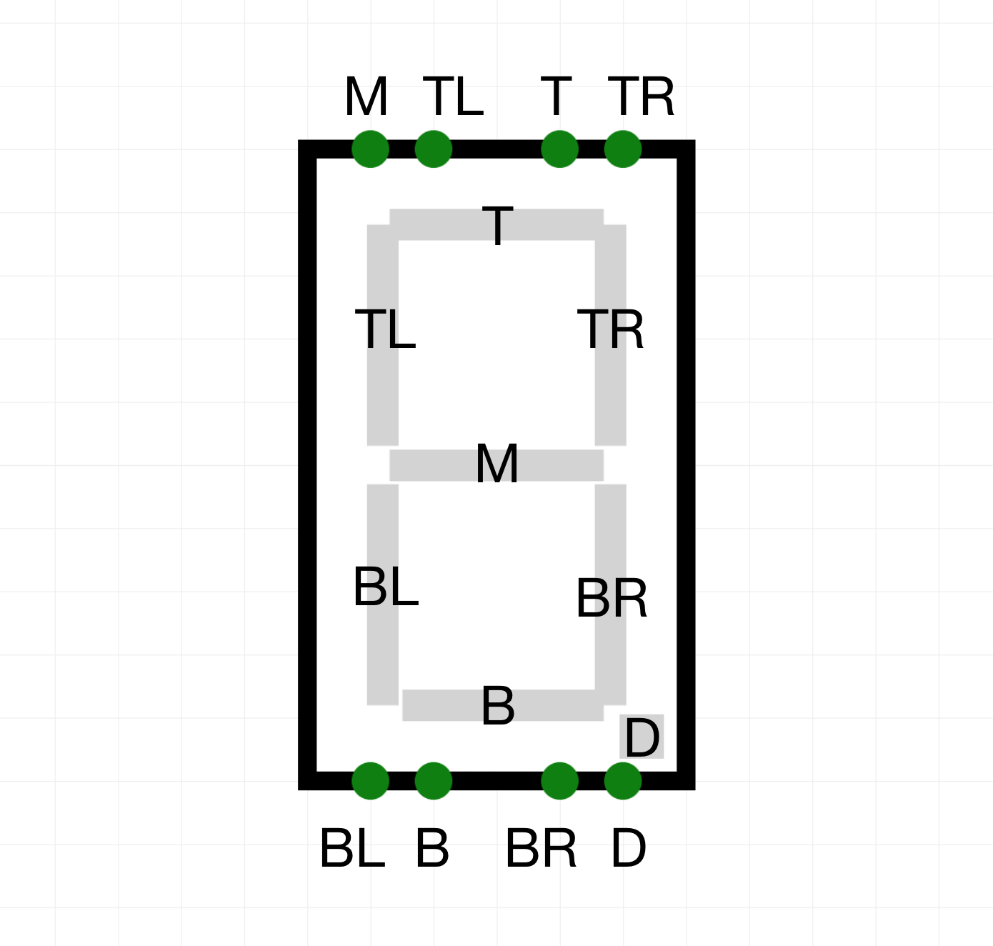
SevenSegDisplay
The SevenSegDisplay behaves similar to a HexDisplay, but it takes an 8-bit input rather than a 4-bit input––making it more customizable. It takes in eight inputs and displays an output, an integer from 1 to 9. As Figure 4.2 elucidates, the top four inputs correspond to the middle, top left, top, and top right segments from left to right respectively. The bottom four inputs correspond to the bottom left, bottom, bottom right, and decimal segments from left to right respectively.
You can verify the behavior of the SevenSegDisplay circuit element in the live circuit embedded below:
Watch this video tutorial to learn more about how to use this circuit element in a circuit.
SixteenSegDisplay
The SixteenSegDisplay takes two inputs and a total of 17 bits: 16 bits in the top input and 1 bit in the bottom input. Each of the 16 bits applied to the top input corresponds to a certain segment in the sixteen segment display. The single bit applied to the bottom input controls the decimal point.
You can verify the behavior of the SixteenSegDisplay circuit element in the live circuit embedded below:
As opposed to the HexDisplay and SevenSegDisplay circuit elements, the main advantage of using a SixteenSegDisplay is that multiple segments can be used to create numbers and letters. However, it requires double the input of the SevenSegDisplay and quadruple the input of the HexDisplay.