Using Subcircuits
As digital circuit designs grow in size and complexity, capturing a large, abstract design at the gate level can become complex, prone to error and require more time for development, synthesis, simulation and debugging.
For a hierarchical design flow, different circuit tabs can be inserted as a subcircuit inside another circuit tab. A subcircuit is a modular functional block that delivers a single function within a given design. This makes the design modular and easy to troubleshoot. As Figure 5.1 elucidates, any changes to the circuit layout must be done before inserting a circuit and making the wire connections. If the node positions within the circuit layout are edited after making the wiring connections, then some of the wiring connections across different nodes or ports in the integrated circuit schematic may be lost.
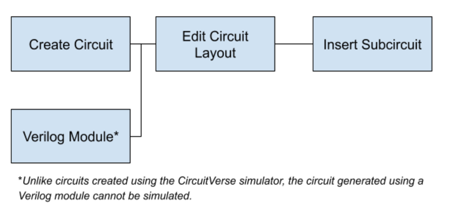
Figure 5.1: Ideal circuit design flow for for an integrated effort while using subcircuits within CircuitVerse
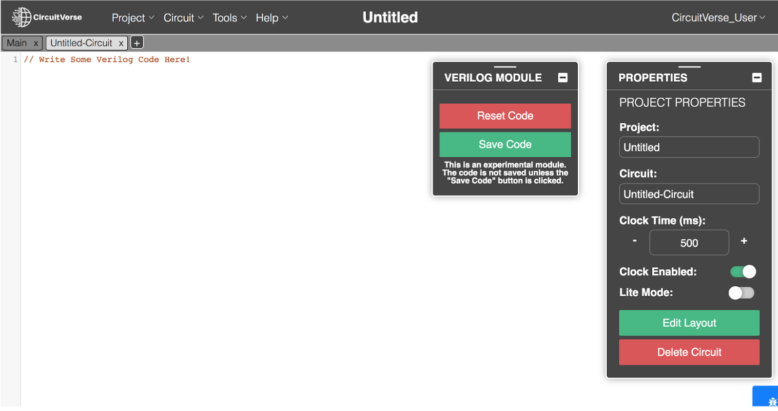
Insert Verilog Modules as Subcircuits
Besides inserting CircuitVerse generated circuit designs, Verilog modules can also be inserted as subcircuits. Users can enter the code in the module interface and save the code to generate the circuit layout (refer Figure 5.2). Unlike CircuitVerse simulations, the circuit generated using a Verilog module cannot be simulated.