Clock Time versus Delay
Before exploring how to visualize a timing diagram for a given circuit, this section explores some key concepts that define the working of the TIMING DIAGRAM panel.
Clock Time (ms):
The Clock Time property attribute in Figure 6.1 refers to the time interval for the half cycle of a circuit. Changing the clock time interval speeds up or slows down the circuit simulation. However, it should be noted that changing the Delay attribute for any circuit element doesn't change circuit behavior. This clock frequency is only for demonstration purposes.
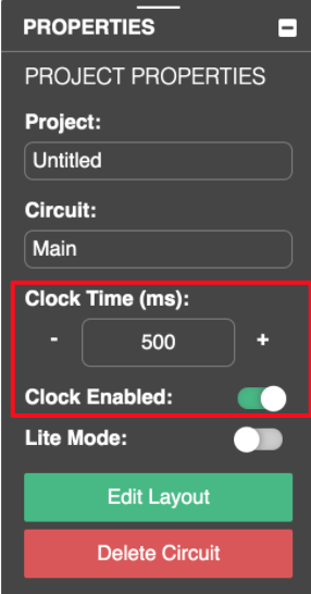
Figure 6.1: The Clock Time(ms) property attribute is the time interval for the half cycle of a circuit
Delay
The Delay property parameter for a circuit element delays refers to propagation delays. It should be noted that the delays are simulated––they are virtual and therefore not rendered.
The Delay parameter doesn't have a unit as delays are processed relative to each other. Unlike the Clock Time (ms) attribute, the Delay parameter changes the behaviour of the circuit and should be used to resolve race conditions. They can be visualized using a timing diagram as described in the next section.
Clock Time and Delay: CircuitVerse Implemented Restrictions
The below design restrictions have been implemented in the CV simulator to ease the design and verification of circuits, without imposing untoward restrictions:
- Real life circuits go into a stable state between clock ticks. Irrespective of any implemented circuit element delays, the circuits go into a stable state between clock ticks. The CV simulator thus cannot simulate circuits that do not go into a stable state between clock ticks.
- Similarly, circuits go into a stable state before processing input signals from different input elements like buttons and stepper.
- Contamination delay = Propagation delay
- Hold time = 0