Best Practices For Working With CircuitVerse Simulator
-
Build in small steps: Let us assume that you are implementing an arithmetic logic unit (ALU). Add a little functionality, then stop and test that functionality by trying out different input values. Once you're convinced that the new functionality works, add a little more functionality and repeat the cycle. If required, work out the logic on paper with a truth table before trying to implement the circuitry. Implement flags as needed. Test the behavior of the flags for different situations.
-
Mind those circuit element properties: Use the PROPERTIES panel smartly while designing your circuit. Consider that you are building an adder that receives eight bits as an input. As Figure 2.57 illustrates, the BitWidth property attribute of the Adder circuit element must be set to eight bits in the PROPERTIES panel. Any input circuit elements connected to the 8-bit adder should also be 8 bits wide. Thus, the BitWidth property attribute of the Input circuit elements in Figure 2.57 has been also set to eight bits.
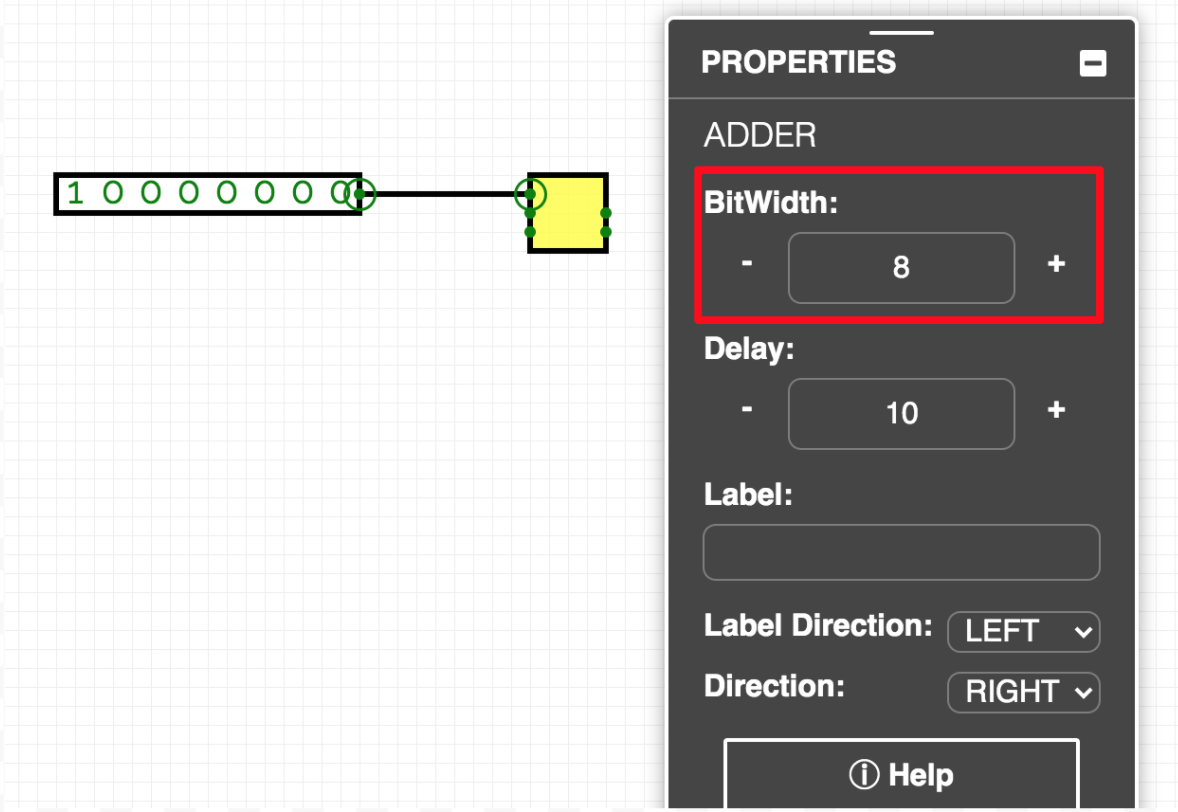 Figure 2.57
 -
Manage your circuit layouts: While building complex design schematics, CircuitVerse highly recommends users to edit layouts of the subcircuits prior to adding wire connections across different nodes. If the node positions within the circuit layout are edited after making the wiring connections, then some of the wiring connections across different nodes or ports in the integrated circuit schematic may be lost.
-
Copy paste your circuits: Cross-project copy and paste is supported to include whole or parts of circuits across different circuit tabs or across different project URLs.
-
Annotate your circuits: As your design goes through multiple revisions, use different annotation tools available within the CircuitVerse simulator to add the version number, date, amendments, and different group members involved. Refer to Chapter 4 to learn more about the different annotation elements available within the CV simulator.