Using Edit Layout
After a subcircuit has been successfully populated, the circuit layout can be edited using the Edit Circuit Layout setting available on the Properties Panel. The Edit Circuit Layout setting generates the circuit layout (with valid input and output connections) as a black box. The circuit elements and the relevant connections are hidden whereas the input and output pins are displayed. This clean design schematic adds more clarity and reduces the cognitive load on the user.
As required, a user can use the LAYOUT ELEMENTS panel to add any circuit elements inside the black box (to observe the behavior of the circuit when the circuit) , and the LAYOUT panel to improve the layout of the circuit. Refer Figure 5.3. Table 5.1 provides a brief description of the different settings available on the LAYOUT panel.
NOTE: Circuit layout must be edited before inserting a circuit or completing the wiring connections. If the node positions within the circuit layout are edited after making the wiring connections, then some of the wiring connections across different nodes or ports in the integrated circuit schematic may be lost.
TIP: Make all the necessary changes within the circuit layout prior to the wiring connections.
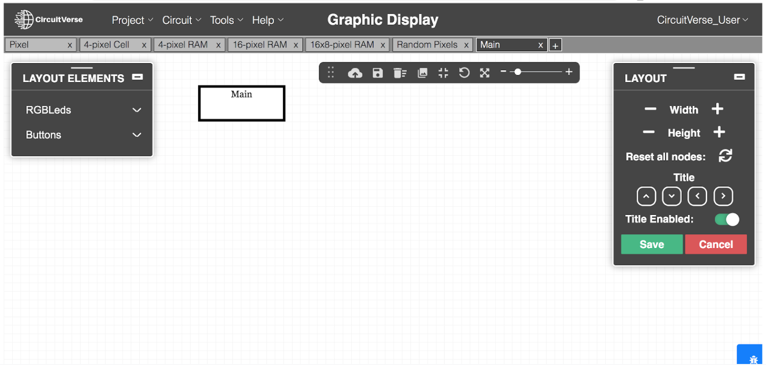
Table 5.1: Brief description of the different settings available on the LAYOUT panel
| Setting | Description |
| Width | Displays a numeric stepper to manage the width of the circuit layout. |
| Height | Displays a numeric stepper to manage the height of the circuit layout. |
| Reset all nodes | Resets the nodes to their default position. |
| Title Enabled | Displays or hides the title of the subcircuit. By default, the title is displayed for each circuit layout. |
| Title Position | Positions the title at a desired location using the up, down, right and left arrows. |
To learn more about how to use subcircuits and Edit Layout for building circuits, refer Chapter 7.