Multi-bit Wires (Buses)
Different circuit elements can be connected by clicking on the output of one gate or port, and dragging the mouse to the input of the next one. While connecting two elements, the wire rubber bands around an angle (refer Figure 3.22). However, if any input of any circuit element is not connected within the circuit, it does not affect the circuit behavior.
Understanding Wire Colors
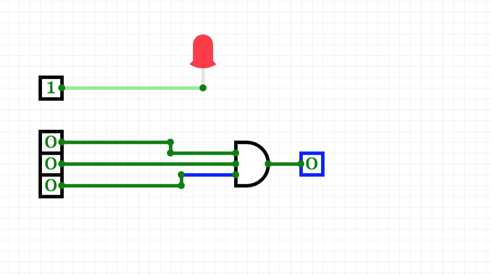
When a wire connects two circuit elements, the CircuitVerse simulator displays different wire colors (refer Figure 3.22) to indicate the bit width status of the wire. As the circuits become more complex, users can study the wire colors to troubleshoot or analyse their circuit behavior in CircuitVerse. Table 3.9 shares a description of the bit width status of the wire for different wire colors.
Table 3.9: Understanding wire colors for different bit width values of a given wire
| Wire Color | Description |
| Blue | The bit width value that the wire is carrying is not known. |
| Dark green | The wire is carrying a one-bit 0 value. |
| Bright green | The wire is carrying a one-bit 1 value. |
| Black | The wire is carrying a multi-bit value but some or all of the bits may not be specified. |
| Red | The wire is carrying an illegal or unknown value. |
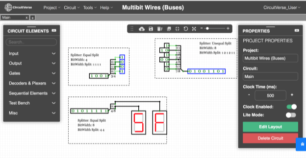
Creating Multi-bit Wires
Most of the circuit elements in CircuitVerse have a bit width value associated with it. While Figure 3.23 illustrates multibit wires being used for splitting and combining multi-bit data into equal and unequal parts using splitters, different circuit elements include different attributes within the PROPERTIES panel to customize the bit widths of their inputs and outputs.